
Recently I purchased a lot of the RFID readers with the name “RFID-RC522” from China. These were sold as using the MFRC522 chip, but on inspection the chip was blank beyond an orientation marker on them. Initial experiments showed that these boards could read the MiFare Classic cards reliably, but I couldn’t get them to read any other card type. I also found the range was somewhat short, especially with smaller coils as used by keyfobs. I searched around a lot to find people recommending all sorts of fixes and workarounds, none of which made sense. For example some suggested running the board a 5v instead of the rated 3.3v, while others said it simply didn’t support any other card types. I checked the MFRC522 chip specifications and confirmed that it did indeed support other card types.
I tried swapping the chip out for a known genuine part, but I still experienced the same issues. So that eliminated the chip as the source of my problems.
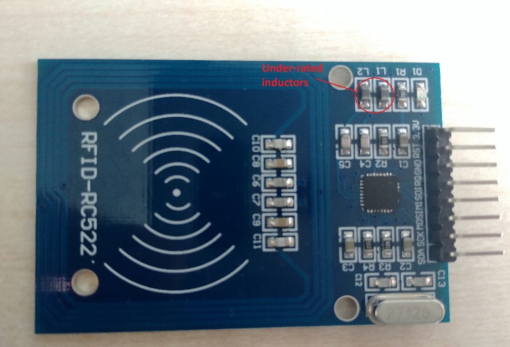
After much digging I came across a blog article that mentioned two inductors L1 and L2 and suggested replacing them with one that is higher rated for current draw. While the tuning value is correct at 2.2uH, they were only allowing through a small amount of the possible power output by the MFRC522 chip. Swapping these over to a part that can handle over 150mA seems to do the trick. I ended up using “Panasonic ELJFC/SC Series Type 1008 Wire-wound SMD Inductor 2.2 μH ±20% Wire-Wound 155mA Idc” which I purchased from RS Components stock code 182-6601. There were suggestions to replace two capacitors as well, but my experiments with this only caused problems rather than improved the reading range. Following the change to these new inductors my read range increased significantly, and it started reading any card I threw at it (of the correct frequency). I was amazed at what it could read, including my bank cards as well as Ultralight and Ultralight C cards.
Before fixing:
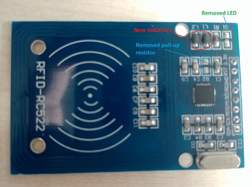
As additional power savings, as this was to be a battery based application, I removed D1 (the power LED), and R2 (the reset pull-up resistor). The power LED is simply showing the board has power, it doesn’t indicate anything about the status of the MFRC522 chip. The pull-up resistor on the reset pin will simply waste power when directly driving that pin from a microprocessor. Removing these components has no negative impact, provided you do drive the reset pin in to the correct state at all times. Pull reset low puts the board in to standby and it draws almost no power in that state.
After all the changes:
I also experimented with the boards based upon the PN532 module. When I located a genuine board from Elechouse it worked amazingly well, reading everything I threw at it with ease. When I used boards purchased from other places I had issues reading any cards beyond the MiFare Classics. I need to look in to why these boards won’t work, it could well be a similar issue – or simply the chips running these boards are fake can’t read all the stated card types.